Field tutorial · ROS 2 · CAN · safety
Adapt a commercial agricultural robot into an open-source platform
Transform a closed weeding robot into a programmable research platform, without replacing the existing mechanics or bypassing hardware safety systems.
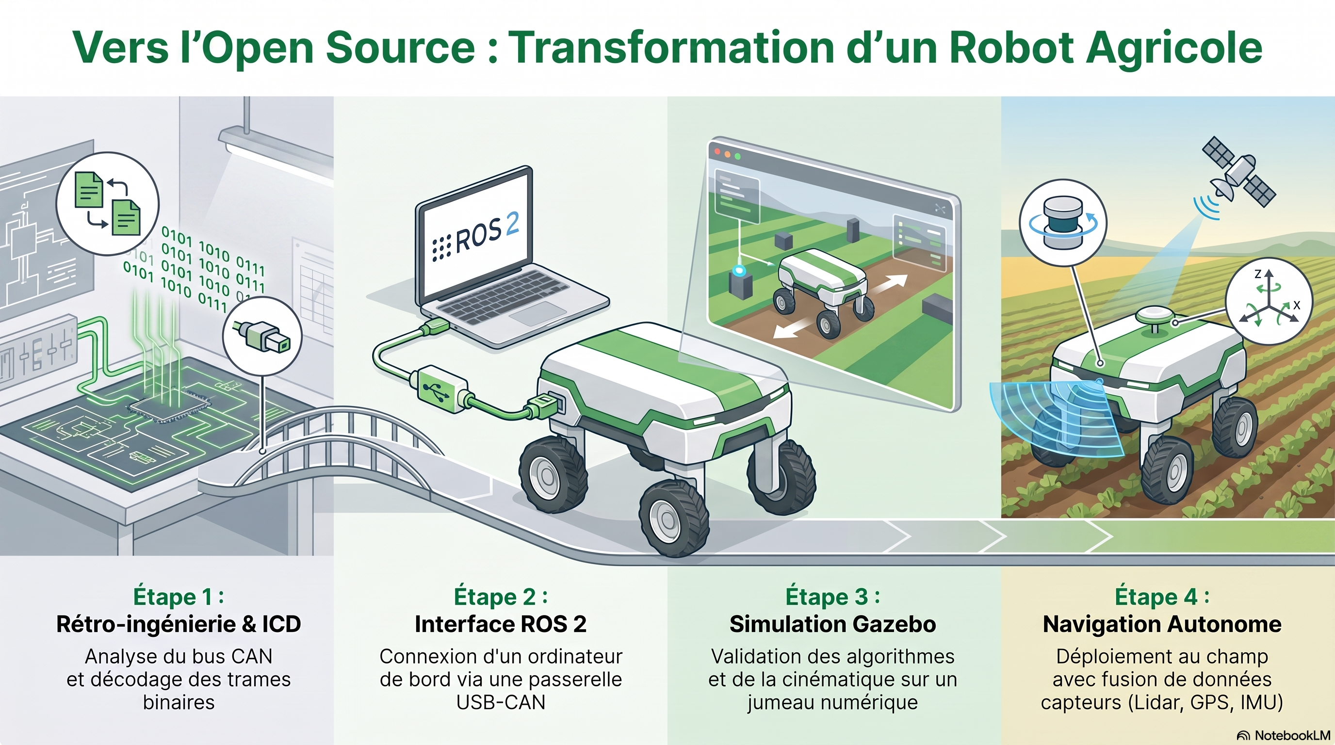
Overview: open the robot without rebuilding everything
Adapting a commercial agricultural robot into an open-source platform does not mean dismantling it and starting over. The more effective idea is to keep the existing mechanical and electromechanical platform, understand its interfaces, then add a new open software layer.
In this tutorial, the starting robot is a Dino, a mechanical weeding platform designed as a closed commercial system. The objective is to turn it into a ROS 2-compatible research robot that can be simulated, teleoperated, instrumented and eventually used to test localization, navigation and control algorithms.
Important: here, “hacking” means responsible reverse engineering and integration. The goal is not to bypass protections, but to create an open interface while keeping hardware safety independent from the new software.
Main ingredients
Existing platform
The robot already provides batteries, mechanics, traction motors, steering actuators, brakes, sensors and safety devices.
CAN + ICD
The CAN network becomes the entry point to actuators and internal feedback, provided that every frame is documented in an Interface Control Document.
ROS 2
ROS 2 breaks the system into nodes: CAN reading, odometry, IMU, GPS, Lidars, kinematic controller, navigation and diagnostics.
What to plan for
- Observation tools: electrical diagrams, bill of materials, robot access, measurement tools and communication logs.
- CAN interface: a commercial USB-CAN adapter or a microcontroller gateway with a CAN transceiver.
- Onboard computer: a Linux machine able to run ROS 2, drivers, the controller and diagnostic tools.
- Simulation: a Gazebo model of the robot to validate conventions before real tests.
- Safety: clear access to emergency stops, bumpers, brakes, fault states and reset conditions.
Understand the robot before commanding it
The first step is reverse engineering. Start from the robot in its original state and progressively rebuild its architecture: electrical subsystems, controllers, sensors, actuators, protocols and safety mechanisms.
Identify
Batteries, safety box, guidance rack, main computer, control boards, operator interfaces and sensors.
Record
Messages exchanged when the robot is idle, driving, turning, braking, resetting safety systems or reporting a fault.
Method tip: start by listening, comparing and annotating. One understood frame is better than ten frames injected at random.
Preserve the original safety systems
An agricultural robot is a heavy and powerful machine. The new ROS 2 architecture may request motion, but it must never prevent the safety system from stopping the robot.
| Keep in priority | Role in the open architecture |
|---|---|
| Emergency stops | They must cut or prevent motion even if ROS 2 behaves incorrectly. |
| Bumpers and guards | They trigger a stop or actuator inhibition when dangerous contact is detected. |
| Brakes and reset logic | They must return to a safe state after power loss, a fault or communication loss. |
| Watchdog and faults | They force a stop if commands are no longer valid or actuators report a problem. |
Simple rule: replace high-level navigation and command logic; do not remove existing hardware protections.
Turn proprietary CAN into a documented interface
The CAN network is the robot's internal language. It carries motor setpoints, actuator positions, states, faults, currents, temperatures and sometimes sensor information. To use it properly, create an ICD, or Interface Control Document.
What the ICD describes
CAN identifier, sender, receiver, length, frequency, byte meaning, byte order, scaling factor, unit, limits and error codes.
How to build it
Listen to the bus with a CAN sniffer, compare frames across robot states, send controlled commands and validate values with physical measurements.
Mini decoding recipe
Listen
Connect the interface in observation mode and record frames without influencing the robot.
Compare
Vary only one action at a time: one wheel, one actuator, one brake, one safety state.
Convert
Reconstruct raw values, then determine the unit and scaling factor.
Document
Centralize results in a clear file instead of scattering conversions across several programs.
Add a new onboard computer
Once the main frames are understood, a Linux computer can be connected to the robot's main CAN bus. The link can use a USB-CAN gateway or a dedicated microcontroller.
USB-CAN adapter
It appears in Linux as a network interface, for example can0. Software can then read and write frames with SocketCAN.
Microcontroller gateway
It receives CAN frames, forwards them to the computer, receives ROS 2 commands and converts them into CAN messages.
Good reflex: at first, the gateway should mostly observe. Command injection only comes after validating the ICD, limits and safety conditions.
Build a modular ROS 2 architecture
ROS 2 separates the robot into independent functions. Each function becomes a node: CAN bus reading, decoding, motor command, steering command, IMU, GPS, Lidars, odometry, localization, navigation and diagnostics.
/cmd_vel
Navigation or teleoperation publishes longitudinal, lateral and angular velocity.
Kinematics
The controller computes wheel speeds and steering angles for the four wheels.
Dino driver
Physical quantities are converted into frames that follow the ICD.
CAN bus
Motor and steering controllers receive the setpoints.
ROS 2 topics
States, faults and measurements return as physical data.
Why it helps: navigation does not need to know the CAN format. It speaks in velocities, poses and states; the low-level driver handles the bytes.
Develop the 4WD-4WS controller
The Dino is not commanded like a small differential robot. Each wheel has an independent speed and steering angle. A global command must therefore become eight setpoints: four wheel speeds and four steering angles.
Car-like / opposite
Front and rear wheels can work in opposition to reduce turning radius.
Crab
Wheels stay parallel to move laterally or follow a row with smooth correction.
Pivot
Wheels orient to allow rotation around the robot center.
This controller is the core of the adaptation: it converts a standard ROS 2 command into setpoints suited to an agricultural platform with four driven and steered wheels.
Validate in simulation before real tests
Before sending commands to the real machine, create a digital twin in Gazebo. Ideally, the simulation should use the same high-level interface as the real robot.
| Check in simulation | Why it is critical |
|---|---|
| Velocity directions | An inverted convention can send the robot in the wrong direction. |
| Steering angles | Wheels must reach the correct orientation in each motion mode. |
| Joint limits | The controller must respect the physical capacities of actuators and mechanics. |
| ROS 2 topics | Teleoperation, navigation and diagnostics must work without changing interface. |
Ideally: in simulation, the low level is ros2_control + Gazebo. On the real robot, it becomes the Dino CAN driver. The rest of the architecture remains identical.
Run progressive tests on the real robot
First tests must be gradual, documented and reversible. Validate one function at a time, keep one person responsible for emergency stop, and log all useful data.
Read only
Read CAN frames, reconstruct states and compare values with observed behavior.
No-load commands
Test actuators at low speed, with wheels raised or in a controlled area, using strict limits.
Limited teleoperation
Send simple commands through ROS 2 and validate motion modes one by one.
Supervised navigation
Add localization, Lidars, GPS/IMU and Nav2 only after the low level has been validated.
Expected outcome: a commercial robot turned into a research platform
At the end of the process, the robot is no longer only a commercial machine dedicated to weeding. It becomes an open platform for testing new control, localization and navigation methods in agriculture.
Obtained functions
Modern onboard computer, ROS 2 architecture, documented CAN interface, 4WD-4WS controller, Gazebo simulation, teleoperation and diagnostic tools.
Possible experiments
Autonomous navigation, GPS-IMU-LiDAR fusion, row following, headland-turn strategies, agricultural perception and predictive maintenance.
Main gain: reuse a robust industrial platform while gaining the flexibility of a modern lab robot.
Final checklist before deployment
- Hardware safety remains independent from ROS 2.
- Emergency stops and bumpers have been tested.
- Critical CAN frames are documented in the ICD.
- Units, scaling factors and limits are centralized.
- The simulation uses the same command interface as the real robot.
- Speeds and angles are limited before CAN emission.
- Motor faults, currents and temperatures are monitored.
- Communication loss leads to a safe state.
- Real tests start at low speed.
- ROS 2 and CAN logs are recorded for each test.
Educational note: any real adaptation of an agricultural robot must be performed by an authorized team, in a controlled environment, while following the machine's safety procedures.